Breadboard
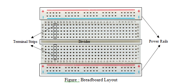
Breadboards as shown in Figure…. are one of the most fundamental pieces when learning how to build circuits. These “solder-less” breadboards [1] are great units for making temporary circuits and prototyping, and they require absolutely no soldering [2]. Another common use of breadboards is testing out new parts, such as Integrated circuits (ICs). The different types of a standard breadboard are as follows: 1. Full-size Breadboard 2. Half-size Breadboard 3. Mini Breadboard. To build an electronic or electric circuit, it is highly recommended to follow a circuit schematic or diagram.

The appearance of all breadboards whether they are of full-size and half-size, have holes, letters, numbers, blue and red lines on them as displayed in Fig……..

Letters: Printed “A” to “J” at the top and bottom of the breadboard. These horizontally letters divide the holes evenly into vertical lines.
Numbers: Printed “1 to 30” on left and right edges on half-size breadboards to identify horizontal rows. Some use skip-counting in fives. The numbers and letters help a person to locate a certain hole during troubleshooting a circuit.
Horizontal Row: These are called “Terminal strips” to connect the electronic components. Each row contains five holes on each side (left and right) separated by a middle divider. Every five holes in the same row are electrically connected, but they must be on the same side.
Vertical Bus: It consists of two vertical columns that are commonly known as “Power Rails.” Every breadboard has two power rails at the ends of both sides. The purpose of the power rails is to connect the circuit to an external power supply. One column is to connect the circuit with the positive voltage (+) and the other column is to connect the circuit to ground (-). Note that breadboards are available from different manufacturers. Some breadboards use coloured lines to identify power rails, other breadboards use coloured lines with plus (+) and minus (-) signs.
In some full-size breadboards the red and blue (or black) lines are broken in half, which means the upper half of the power rails is electrically isolated from the lower half to enable the use of one breadboard to connect two different circuits. If one has to connect the two halves together, it can be done using jumper wires. Also, the power rails on the left side are isolated from the second set of power rails on the right side
Divider: A middle divider or “ravine” that runs vertically divides the breadboard symmetrically into left and right sides. The halves of the breadboard are electrically isolated from each other by the middle divider.
Almost all components that have leads and are known as THT (through the hole technology) components can be used on breadboards. Since there is no need for soldering, we can connect the components simply by pushing the leads into the hole’s metal clips.


